Do’s and Don’ts for Laying Track
by Steve Gillett
The number one goal of laying track is to end up with a module or layout that operates trouble free. Once a
track plan has been developed, it is time to do the construction engineering to determine exactly how to properly
lay, connect, wire and ballast the track. To obtain this result you must become proficient in four areas: track
geometry, track installation, soldering and ballasting.
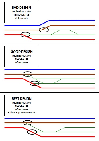
- Turnout alignment – As you design your layout, the main line should always follow the straight (closed) leg of a turnout, with the siding taking the diverging (thrown) leg. One of the most frustrating events when operating on a layout is having an engine or car that picks the point of a turnout and derails. When the train runs straight, it is less likely to pick the point of a turnout.
- Crossings – This tip is simple. AVOID crossings whenever possible. If you must have them, design your track plan to use as close to a 90° intersection as possible. The smaller the angle, the more likely the chance of a derailment. 7½° and 15° crosses are an accident waiting to happen.
- Reverse or Ogee Curves – There must be a straight section of track between the curves that is as long as the longest car you might run. In N-Scale, that means a 7” straight section.
- Transition Curves – Just like real railroads, whenever space permits, track should ease into a curve. There are several books that provide detailed instructions for this technique. Although transition curves are critical in full scale railroading, they are inconsequential in model railroading and their absence does not affect performance. Details on transition and ogee curves can be found in the "N-Trak Module How-To Book", chapter 4, published by N-Trak Model Railroading Society, Inc.
- Grade changes – Planned and designed grade changes must be gradual. Track kinks can occur vertically as well as horizontally. Use flex track as you transition from one grade to another. Along the incline the grade should be constant. A sudden depression or rise of the rails can cause a mis-alignment of the couplers between two cars and will often result in their uncoupling. This problem can also occur on flat stretches of track that are laid on a foam base. If someone leans on a finished section of track and depresses the foam, it won't rebound.
Flex Track Installation: With rare exceptions factory made track is in gauge and undamaged. The challenge is to
ensure that the same thing is true after the track is joined and laid. Poor soldering techniques can melt plastic ties
and improperly installed track nails can bend plastic ties. Damaged ties can result in out-of-gauge track. Improper
alignment of rails and rail joiners will allow track to kink at the joint. Here are some ways to avoid these issues.

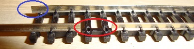
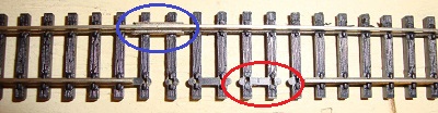
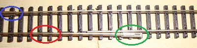
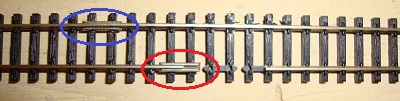
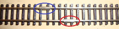
- Stagger rail joiners whenever possible. When a rail joint on one rail is opposite continuous rail, the likelihood of kinking is minimized, particularly on curves. When laying flex-track this is very easy to do. Slide the free rail back five ties. Trim off the “nail” head from the 4th and 5th ties. Connect the fixed rails in the normal fashion. Slide the free rail of the other piece of flex track through the nail heads of the first three ties and continue to slide it along side of the other sliding rail. This allows easy attachment of the joiner to the sliding rail. Then slide the rail back, positioning the joiner over ties 4 and 5. Insert the other sliding rail into the joiner. I recommend that you make up several pairs of staggered, two flex-track sections before beginning to lay track. Do not make three section sets if they are to go on a curve because bending the section requires the rail joiner to re-locate, which it cannot do because of the nail heads. Add additional flex-track sections (one at a time on curves) using the same staggering technique. In N Scale, one staggered, two flex-track section can make a 90° curve with a 36” radius. This allows you to avoid having to make additional solder connections on the curve.
- Glue down your track using a thin film of white glue. Tack the track in place with track nails, but only insert them half way. Once the glue has dried, remove them. The white glue should be considered a temporary adhesive that holds the track in place until you can lay ballast.
- Some modelers believe that straight track with a little waviness in it adds a sense of realism and the look of age. That may be true and generate an artsy and aesthetically pleasing scene, but it is also an invitation for derails. When laying straight runs of track, use a long metal bar, such as a 4’ aluminum yardstick as a guide. Lay the guide against the outside of one rail and push the track against it until the rail is in contact with the guide over the entire length of the run.
- When laying parallel tracks, lay one track, let the glue dry, and then use a jig with rail grooves in it to align the parallel track. The Deluxe re-railing ramp has these grooves cut on one side. Using them, you will get parallel tracks that are the N-Trak standard of 1½” apart, center to center. You can make a jig out of a small scrap of 1” x 4” wood and cut rail grooves for any spacing you desire. (See N-Trak Tips – Track Spacing Tool)
- Use an NMRA track gauge to confirm that the rail spacing is correct, particularly near rail joiners. Since white glue is water soluble, it’s easy to re-locate any track that needs tweaking, removal, or straightening. Simply spritz it with a 50/50 mix of rubbing alcohol and water to re-hydrate the glue and fix what needs fixing.
Soldering: It takes juice to make the trains go. If the electrons can’t flow freely, the engines will not
perform properly. Good electrical conductivity is totally dependent on properly soldered connections.
- Use rosen core solder. The rosen flux in the solder is rarely enough to ensure a good bond. Before soldering, apply additional flux to the solder point with a toothpick.
- Always apply solder only to the outside or bottom of a rail, NEVER TO THE INSIDE! Be sure the rail is clean before soldering. If the rail has been painted, remove the paint from the area that will be soldered. If the solder beads up, you will not have good electrical contact. This will happen if the metal is not clean, if the metal is not hot enough or if the solder does not have an acid flux core. A good solder joint occurs when the solder thins and flows down into the rail joiner.
- When soldering a rail joiner or a feeder to a rail, just hold the tip of the soldering iron to the rail. Be careful not to press too hard against the rail because that could push the rail toward the center of the track and cause a tight spot.
- To provide maximum electrical conductivity, all rail joiners should be soldered to the rails they connect. However, on larger layouts, you must leave small gaps in the track every 8’ or so to allow for expansion and contraction. This is not necessary on N-Trak modules because there is a natural break where the modules are connected to each other.
- For maximum current flow, track feeders should be soldered to both rails every two feet on N-Trak modules and to both rails of every joint of track on home layouts.
Ballasting: Laying ballast is the final step in the track laying process. When done properly it not only adds a
finished look to the track, it also becomes the primary device that permanently holds the track in place. Unfortunately,
if ballast is poorly applied, it can be a primary cause for derails.
- It is much easier to add ballast than to remove it! So, ballast your track conservatively until you have mastered the technique.
- Mastering the technique is the key! If you have not reached a skill level with which you are confident, practice on scraps of track until you get it figured out.
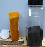
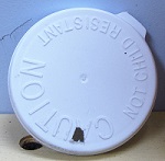
- Get a tall plastic medicine bottle with a snap on cap (not a safety cap). You can get these from your local Walmart pharmacy. Cut a small triangle in the lid next to the edge so that a controlled amount of ballast can pour out of the bottle when tipped. Load the bottle with ballast and snap on the lid.
- Run the bottle along the track allowing ballast to pour onto the track between the rails in a heap. Then run your finger between the rails causing the ballast to spill over the rails and fall on the outer side of the ties.
- Take a 1" soft paint brush and gently sweep between the rails so that no ballast is above the ties. This action will also do the same outside the rails. Repeat the sweeping until the ballast between the rails looks good.
-
Using the brush, push the ballast that has spilled outside the rails up against the ties. If more ballast is needed to cover the roadbed, make a run with the bottle placing the hole in the lid just outside the rails. Then repeat the sweeping action to that area until the ballast is where you want it.
- BE PATIENT. Steps 4-6 take a while. Again, ballast conservatively. It’s easier to add more ballast than to remove excess ballast. Before moving to step 8, check all flangeways, making sure that there are no grains of ballast in them. Also check all turnouts to be sure no grains of ballast interfere with the smooth operation of the points.
- Once you get the ballast spread the way you like it and are ready to apply glue, first thoroughly soak the ballast with a mixture of 50/50 water and rubbing alcohol (commonly called “wet water”) using a spray bottle. Spray from a distance so that the wet water doesn’t have velocity that might jet the ballast from where you want it. Then apply the glue between the rails with an eye dropper or similar device. The alcohol in the wet water reduces the surface tension of the glue so that it will not bead up, but will flow easily and soak into the ballast. Apply the glue slowly so that it seeps under the rails and down the sides of the track. If too much glue is applied it could begin to run down the side, making rivulets in the ballast. Many modelers use a 50% diluted solution of white glue and water. This works well, but white glue leaves a film on the ballast. A better product is undiluted Woodland Scenics scenic cement which dries clear.
- If you are ballasting along turnouts, work the switches while the glue is drying to keep them from sticking. If they become stuck, just spray them with wet water and work them to unstick them.
- Once the glue has dried, you may find that a second application of glue is required. If so, don’t forget to spritz wet water again before applying the glue.
- After you have ballasted your track, you must be sure that no ballast remains above the ties or glued to the inside of the rails or flangeways. Take a flat-bladed screwdriver and firmly draw it along the inside of both rails to knock off any stubborn flecks of ballast.
- Carefully inspect all turnouts and crosses. Be sure no grains of ballast interfere with the operation of the points or are stuck in the flangeways.